Every reverse engineering project starts with information about the original part. The data required for reverse engineering usually includes a physical sample, any existing CAD drawings, material specifications, dimensional measurements and the conditions the part works under. The better this input, the closer the new part will match the original.
For manufacturers, OEMs and product development teams, collecting the right information up front reduces design errors, avoids repeat prototypes and shortens development time.
A missing drawing or incomplete specification does not stop a project. Engineers can recover much of the lost design information through 3D scanning, material analysis and CAD reconstruction. What you are able to provide decides which reverse engineering procedure the engineering team will follow.
Table of Contents
- Reverse Engineering Data Checklist: 8 Things to Prepare
- 1. Why Is a Physical Sample Important in Reverse Engineering?
- 2. Which CAD Files and Engineering Drawings Should You Share?
- 3. Material Specifications: Grade, Hardness and PMI Testing
- 4. What Dimensional Measurements Are Required for Reverse Engineering?
- 5. Operating Conditions: Load, Temperature and Environment Data
- 6. What Performance and Reverse Engineering Requirements Should You Define?
- 7. Manufacturing Information: Process, Quantity and Quality Standards
- 8. Why Share Failure History and Damage Details?
- 9. How Is Your Design Data Protected? NDA and IP Rights
- 10. Reverse Engineering Process: 7 Steps After You Share the Data
- 11. What Reverse Engineering Documentation Will You Receive?
- 12. What If Drawings, CAD Files or Specifications Are Missing?
- 13. Reverse Engineering for Indigenisation of Imported Parts in India
- Key Takeaways
- Conclusion
- Frequently Asked Questions About Reverse Engineering Data
Reverse Engineering Data Checklist: 8 Things to Prepare
What you need to gather changes with the component, its application and the manufacturing process planned for it. A single machined bracket needs far less information than a complete industrial assembly with moving parts.
Use the checklist below to gather what you have before contacting an engineering team.
| Required data | Why it matters |
| Physical component or sample | Gives a reference to inspect and measure |
| CAD files and drawings | Shows what design information already exists |
| Material specifications | Tells engineers what the part is made of |
| Dimensional measurements | Defines component geometry and tolerances |
| Operating conditions | Explains how the component is used |
| Performance requirements | Defines the expected function |
| Manufacturing details | Shapes production planning |
| Failure history | Points to design or material problems |
With these details in hand, engineers know where to start. They can also see early what is missing and plan how to recover it before work begins.
1. Why Is a Physical Sample Important in Reverse Engineering?
A physical sample gives engineers a direct reference for the original component’s shape, dimensions and construction.
When original CAD files are unavailable, the sample becomes the main source of design information. Engineers inspect its geometry, surface condition, assembly features and signs of wear.
When submitting a sample, include:
- The original component, if available.
- All mating parts from the assembly.
- More than one sample if variations exist between batches.
- Photographs from several angles.
- Notes on damaged or worn areas.
- Specifics about the machine or equipment from which this part originated.
A worn or broken part can still be used. Engineers will, however, need to separate original design features from damage caused in service, so any extra reference such as an old photograph, a catalogue page or an identical part from another machine is worth sending.
2. Which CAD Files and Engineering Drawings Should You Share?
Existing CAD files and drawings save a lot of guesswork, because they record the original design.
They show dimensions, geometric features, how parts fit together and how the part was made. They also cut down the manual measures needed during reconstruction.
Share any available files, including:
- 2D engineering drawings.
- 3D CAD models.
- STEP and IGES files.
- STL scan or mesh files.
- Assembly drawings.
- Manufacturing and fabrication drawings.
- Previous design revisions.
Native files from SolidWorks, CATIA or Creo are useful, but neutral formats such as STEP work just as well.
Even incomplete or outdated drawings are worth sharing. Engineers can compare them with the physical sample to find missing dimensions or later design changes.
3. Material Specifications: Grade, Hardness and PMI Testing
Material specifications tell engineers what the new part should be made from. Material choice affects strength, durability, corrosion resistance, weight and operating performance.
If the original material specification is unavailable, engineers may need to identify and test the material before choosing a replacement grade.
Prepare the following information:
- Original material grade, if known.
- Alloy composition and material certificates.
- Hardness requirements.
- Heat treatment details.
- Corrosion and wear resistance requirements.
- Surface coating or finishing specifications.
Positive Material Identification (PMI) uses techniques such as X-ray Fluorescence (XRF) and Optical Emission Spectroscopy (OES) to identify alloy composition. OES can also measure carbon content, which XRF cannot detect. Hardness testing, commonly reported on the Rockwell (HRC), Brinell or Vickers scales, shows how well the material resists indentation and can indicate whether the part was heat treated.
These tests are common for parts from industrial machinery, automotive systems and power sector equipment. Venttup’s reverse engineering services include PMI and hardness testing to confirm the material before the part is reconstructed.
4. What Dimensional Measurements Are Required for Reverse Engineering?
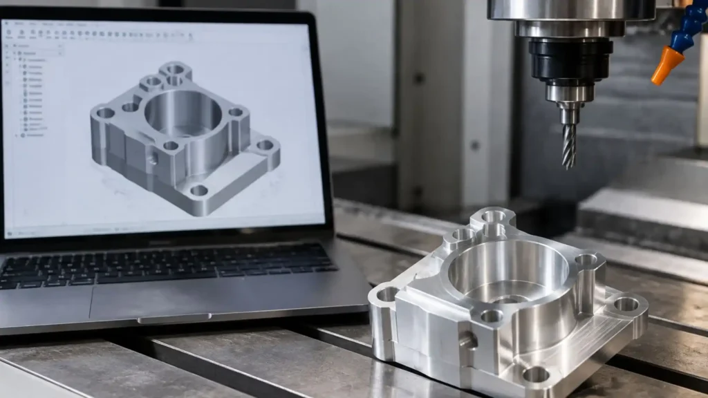
Dimensional measurements define the geometry and fit of a component. Good measurements let engineers rebuild its physical structure as a digital CAD model.
Measurement data to collect includes:
- Overall length, width and height.
- Hole diameters and positions.
- Wall thickness.
- Angles and radii.
- Thread dimensions.
- Surface profiles and surface finish.
- Geometric tolerances.
- Critical mating dimensions.
For precision components, engineers may use digital vernier calipers, micrometers, height gauges, depth gauges and coordinate measuring machines (CMM).
Structured-light and laser 3D scanners work well on curved surfaces, complex profiles and fine detail. They record the surface as a point cloud or mesh, which becomes the base for CAD reconstruction. Where a part has internal passages or hidden features, industrial CT scanning can capture internal geometry without cutting the part open.
Geometric Dimensioning and Tolerancing (GD&T), defined in standards such as ASME Y14.5, sets the acceptable variation in form, orientation and position. If your part has no drawing, tell the team which surfaces are critical for fit so the right tolerances are applied. Non-critical dimensions are often toleranced using a general standard such as ISO 2768.
Venttup combines manual measurement with 3D scanning to support CAD reconstruction and inspection.
5. Operating Conditions: Load, Temperature and Environment Data
Operating conditions show engineers what the component goes through in service. A recreated part has to do the same job as the original, and matching its outer shape is only part of that.
Share information about:
- Operating temperature.
- Working pressure.
- Applied loads and forces.
- Rotational speed.
- Vibration levels.
- Exposure to chemicals or moisture.
- Operating cycles and service life.
- Assembly and installation conditions.
For example, a component used in a high-temperature industrial machine may need a different material and design from a component used in a low-load application.
Engineers use this information during design validation. Finite Element Analysis (FEA) can evaluate stress, deformation, load distribution and thermal behaviour under defined conditions.
Sharing operating data early shows design limits before any metal is cut.
6. What Performance and Reverse Engineering Requirements Should You Define?
Performance requirements explain what the reconstructed component must achieve during operation. They decide whether the project calls for an exact copy or an improved design.
Document the following:
- Expected load-bearing capacity.
- Required strength and durability.
- Dimensional accuracy.
- Functional and assembly requirements.
- Weight restrictions.
- Expected operating life.
- Maintenance requirements.
- Opportunities for design improvement.
For example, an OEM may want to recreate a discontinued machine component while improving its wear resistance. Engineers then need to understand both the original design and the performance the OEM now expects.
Well-defined requirements also settle whether the original geometry stays as it is or gets modified.
7. Manufacturing Information: Process, Quantity and Quality Standards
Manufacturing information makes sure the new design can actually be produced with the processes and materials you plan to use.
Share details about the intended production method, quantity and quality requirements.
Manufacturing inputs to share include:
- Preferred manufacturing process.
- Expected production quantity.
- Prototype requirements.
- Surface finish specifications.
- Inspection and quality standards.
- Assembly requirements.
- Available manufacturing equipment.
Manufacturing processes such as CNC machining, casting, forging, sheet metal fabrication and injection moulding each have their own design rules.
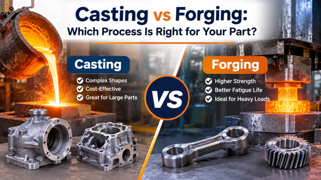
For example, a part designed for casting needs draft angles and fairly uniform wall sections, while the same part machined from bar stock does not. Our guide on casting vs forging explains how process choice affects part design.
Venttup manufactures through a partner network covering CNC machining, casting, forging, injection moulding and sheet metal fabrication. When production needs are known early, the part is designed for the process that will make it.
8. Why Share Failure History and Damage Details?
Failure history tells engineers why the original component stopped working or developed defects.
This matters most when the part being reverse engineered is damaged or obsolete.
Provide details such as:
- Location of cracks or fractures.
- Areas showing excessive wear.
- Corrosion or deformation.
- Previous repair history.
- Frequency of component failure.
- Operating conditions at the time of failure.
- Photographs of damaged areas.
Failure analysis can reveal weaknesses in the original design. Engineers can then assess whether material changes or design modifications are needed.
For example, repeated cracks around a mounting hole may indicate a local stress concentration. FEA can map the stress around that hole and test design changes before a new part is made.
9. How Is Your Design Data Protected? NDA and IP Rights
Samples and drawings often carry proprietary information, so agree on confidentiality before anything changes hands. At Venttup, the NDA is signed at the inquiry stage, before any sample or file is sent. It covers:
- The physical samples you send.
- Drawings, CAD files and scan data.
- Models, reports and drawings produced during the project.
- All project communication.
Also confirm that you have the right to reproduce the part. This is usually clear for:
- Your own legacy designs whose drawings have been lost.
- Obsolete spares whose original supplier has closed or stopped making them.
- Parts for machines and equipment that you own.
If the part is covered by an active patent or by a supplier’s licence terms, speak to your legal team before the project starts.
10. Reverse Engineering Process: 7 Steps After You Share the Data
Once the data is in, the reverse engineering procedure at Venttup runs in seven stages, from NDA to production transfer.
| Stage | Engineering activity | Expected output |
| 1. Inquiry and NDA | Review requirements and sign a confidentiality agreement | Signed NDA and project scope |
| 2. Disassembly and inspection | Label and photograph parts, record wear and assembly sequence | Inspection records |
| 3. Measurement and scanning | Capture dimensions with gauges and 3D scanners | Measurement logs and point cloud data |
| 4. Mesh-to-CAD conversion | Build a parametric model and rebuild damaged features | 3D CAD model |
| 5. Material testing and simulation | Identify alloy, test hardness and run FEA where needed | Material and FEA reports |
| 6. Prototype build and verification | Produce pilot parts and run first article inspection against the CAD model | Prototype and inspection reports |
| 7. Documentation and production transfer | Prepare drawings, BOM and supplier package | Production-ready data |
The exact workflow depends on component complexity, the data available and the order quantity. Once the prototype is approved, production is managed through Venttup’s GATE process (Gate-0 to Gate-7), which covers supplier selection, pilot production and mass production.
11. What Reverse Engineering Documentation Will You Receive?
At the end of the project, you should receive a full documentation pack, detailed enough for a qualified supplier to manufacture the part. Typical deliverables include:
- Native 3D CAD files plus neutral formats such as STEP and IGES.
- 2D engineering drawings with GD&T.
- Point cloud data, scan reports and measurement logs.
- Material identification (PMI) reports and hardness results.
- FEA reports, where required.
- Inspection reports comparing the prototype with the CAD model.
- Bill of materials (BOM) and manufacturing documentation.
Ask for native CAD files as well as neutral formats. This keeps the design editable and avoids being tied to a single supplier.
12. What If Drawings, CAD Files or Specifications Are Missing?
A project can still start when drawings, CAD files or material specifications are missing. A gap in the data changes how the work is done, not whether the project can go ahead. Each missing input has its own way back:
- No drawings or CAD files: the physical part becomes the reference, and 3D scanning plus manual measurement rebuild its geometry.
- No material specification: PMI and hardness testing identify the alloy and its condition.
- No performance data: engineers work out loads and functions from the assembly, the operating conditions and, where needed, FEA.
- No physical sample: photographs, archived drawings or old measurement records can stand in, though more checks are needed.
- Only a damaged sample: worn or broken features are rebuilt in CAD using the mating parts as a guide.
Before starting, tell the engineering team what is unavailable so they can plan how to fill each gap. Venttup’s reverse engineering services cover obsolete components and parts with no original drawings.
13. Reverse Engineering for Indigenisation of Imported Parts in India
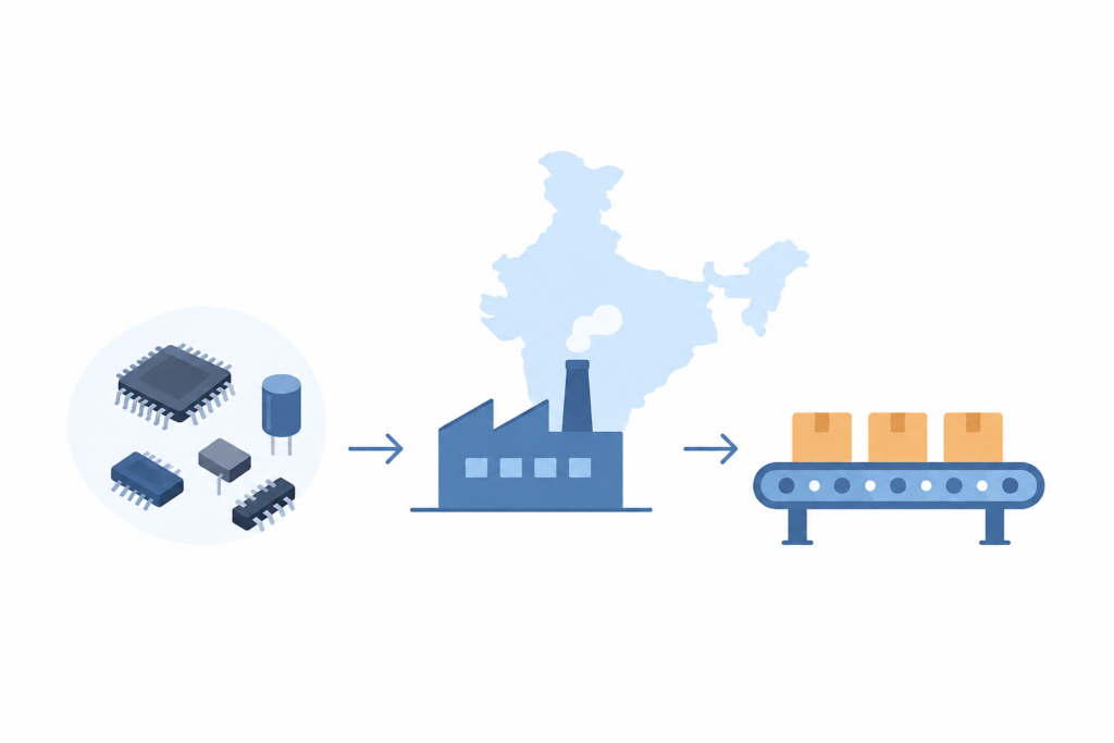
Many Indian OEMs and utilities still rely on imported spares for power, railway, defence and EV equipment. Reverse engineering lets these parts be redesigned and made in India. The usual triggers are:
- The overseas supplier has discontinued the part.
- Import lead times are long or hard to predict.
- A single foreign source leaves the supply chain exposed.
- Customers or tenders ask for higher local content.
The same data checklist applies, with a few extra steps:
- Match the design to materials and grades available in India.
- Check it against the standards the customer specifies.
- Find and qualify local suppliers for each manufacturing process.
- Run type tests or qualification trials where the end customer requires them.
For companies supplying government buyers, higher local content can also improve eligibility for purchase preference under India’s Public Procurement (Make in India) Order.
Read more in our guide to localised manufacturing.
Key Takeaways
- A physical sample is the most useful reference when drawings are missing.
- Share every drawing and CAD file you have, even outdated or incomplete ones.
- Material grade, hardness and heat treatment matter as much as geometry.
- Operating conditions and failure history let engineers improve the part instead of only copying it.
- Tell the team the production process and quantity early, because both affect the design.
- Sign an NDA before sharing samples, and confirm you have the right to reproduce the part.
- Missing information can be recovered through scanning, measurement and material testing.
Conclusion
A reverse engineering project is only as good as the information behind it. The more of it you collect before the first call, the fewer assumptions engineers have to make and the fewer prototypes you pay for.
If you are planning to recreate or localise a component, start by pulling together the technical data you already have.
Venttup Ventures supports businesses with reverse engineering, engineering design, component localisation and manufacturing. Share your sample or drawings under NDA and get a free reverse engineering assessment.
Frequently Asked Questions
1. What is the data required for reverse engineering?
Engineers generally need a physical sample, any available CAD drawings, material specifications, dimensional measurements, operating conditions and performance requirements. The exact inputs depend on the component and its application.
2. How much does reverse engineering cost?
There is no fixed price. Cost depends on the size and complexity of the part, the number of components in the assembly, the tolerances required, the material tests needed and whether prototypes are included. A simple bracket and a gearbox housing with internal passages can differ several times over in effort.
3. How accurate is 3D scanning for reverse engineering?
Metrology-grade structured-light and laser scanners typically measure to within a few hundredths of a millimetre. That is enough for most surfaces, but tight-tolerance features such as bearing bores, threads and sealing faces are usually checked with a CMM, micrometers, bore gauges or thread gauges.
4. Which industries use reverse engineering the most?
Power and energy, railways, defence, aerospace, automotive, EV and shipbuilding, where equipment stays in service for decades and spares often outlive their original suppliers. Venttup works with clients in energy, EV and charging, aerospace, defence, automotive, medical devices and shipbuilding.
5. How much time does it usually take to complete a reverse engineering project?
It depends on part complexity, the data available, the testing needed and whether prototypes are required. A simple machined part moves much faster than a multi-part assembly with no drawings. A realistic timeline is usually shared after the initial assessment.
6. What is the difference between reverse engineering and indigenisation?
Reverse engineering recreates the design data of an existing part: its geometry, material and tolerances. Indigenisation is the wider job of making that part locally, which also covers choosing Indian suppliers, qualifying the part and moving it into regular production. Reverse engineering is often the first step of an indigenisation project.